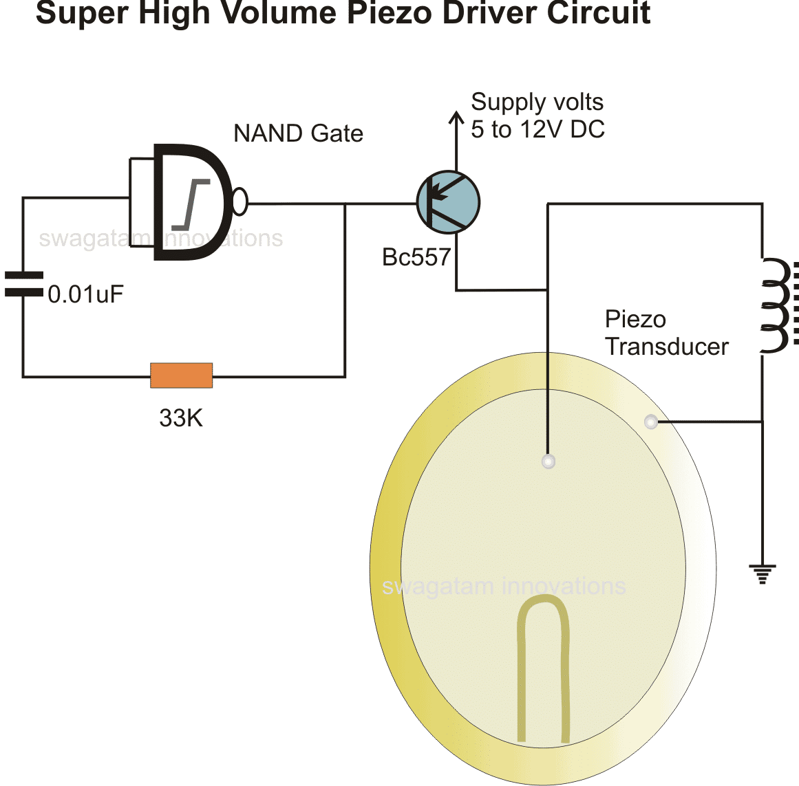
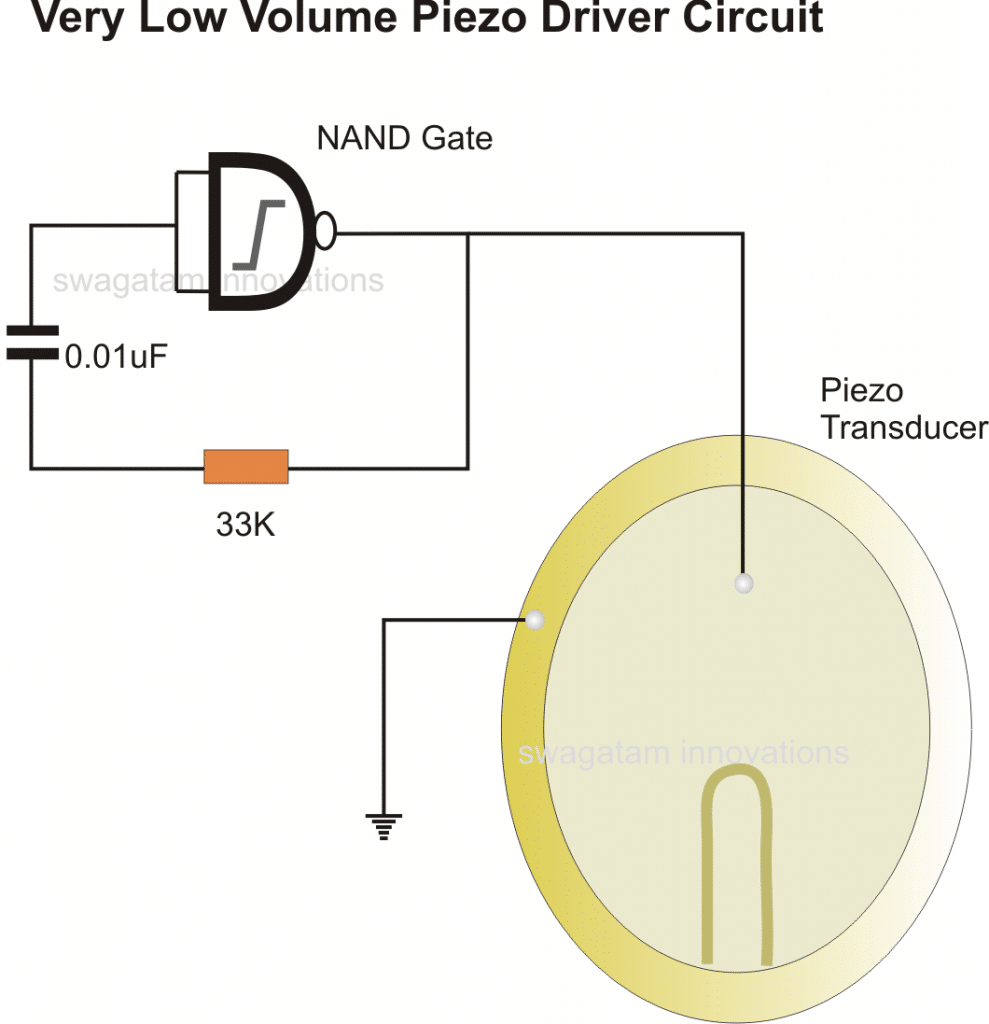
Simplest Piezo Driver Circuit Explained Circuit Diagram A simple piezo transducer driver circuit or a simple piezo alarm circuit is shown in the following circuit using a NAND gate. from an old CO sensor board I removed a piezo-speaker. Now I would like to know if it is an active one or needs a driver circuit like these mentioned above. yes the last design can be used for the purpose but the
applications. Piezoelectric materials generate an electrical charge in response to mechanical movement, or vice versa, produce mechanical movement in response to electrical input. This report discusses the basic concepts of piezoelectric transducers used as sensors and two circuits commonly used for signal conditioning their output. Contents

Understanding Piezoelectric Accelerometer Basics Circuit Diagram
In this tutorial, we are making a project of a Simple sensitive knock sensor circuit. This circuit will blink three LEDs giving you a visual indication when any knock or vibration is detected at the place where this circuit is placed. The knock sensing is done by a piezoelectric sensor. A piezoelectric sensor or PZT is a device that can Understanding Piezoelectric Sensors: The Piezoelectric Effect. The first key aspect of piezoelectric accelerometers is the piezoelectric effect. In general, a piezoelectric material can produce electricity when subjected to mechanical stress. Conversely, applying an electric field to a piezoelectric material can make it deform and generate a

Piezo sensor. Piezo sensor technical data sheet. My assignment is to make make a circuit on breadboard with piezoelectric film sensor, connect it to microcontroller, convert data with ADC and then print results in console, something like this: Piezoelectric Sensor Circuit - YouTube,but in my case ADC is on microcontroller. Converting with ADC and printing data is another story, my problem is
Simple piezoelectric sensor circuit Circuit Diagram
Connection: Connect the signal output pin to the input of an amplifier or an analog-to-digital converter (ADC) to read the voltage generated by the sensor. The ground pin should be connected to the ground of the circuit. Signal Conditioning: The output from a piezo sensor is typically a weak signal and may require amplification. Use an operational amplifier (op-amp) for signal conditioning if Some piezo sensor's include weights at the end to help encourage vibration. AC Voltage Source. Piezo sensors are unique because they produce an alternating current (AC) voltage when stressed, converting mechanical energy to electrical. If you hooked an oscilloscope up to a piezo sensor, you might see waveforms like this when the sensor shakes: The range of measurement: This range is subject to measurement limits. Sensitivity S: Ratio of change in output signal ∆y to the signal that caused the change ∆x. S = ∆y/∆x. Reliability: This accounts to the sensors ability to keep characteristics in certain limits under set operational conditions. Besides these, some of the specifications of piezoelectric sensors are a threshold of
