A simple module to handle timers in microcontrollers Circuit Diagram Electronics projects based on ATmega32 microcontroller of AVR series. These ATmega32 projects and tutorials are explained with the help of schematics, source codes and videos. In this project we are going to design a simple Alarm clock using ATMEGA32 timers. ATmega32A microcontroller has a 16 bit timer… July 15, 2015. 4x4 Keypad
Timer 0 is one of the main timers/counters in the 8051 microcontroller, used for doing timing operations and counting events. It is divided into two 8-bit registers they are TL0 (Timer 0 Low byte) and TH0 (Timer 0 High byte). By combining both, these form a 16-bit timer/counter. TL0 (Timer 0 Low Byte) TL0 is the lower 8-bit register of Timer 0. Specific Design Goals As mentioned already, the primary objective of the first laboratory is to design a digital clock on a 4 LED display using 8-bit 8051 microcontroller. The target system is expected to perform sixty seconds counts, i.e., for example counting from 00:00 to 00:59 in one second interval and repeating the counts one
PDF Lab 2: 8051 Circuit Diagram
In the internal clock mode, Timer0 operates as a timer and uses the internal (FCPU) clock with or without a pre-scaler. The pre-scaler is an integer value that divides the CPU clock to give the Timer Clock, i.e., Timer Clock = FCPU/pre-scaler. When the pre-scaler is set to one or bypassed, the timer runs on the same clock as the CPU is running.
The preloader value of the Timer bit can also be adjusted using pushbuttons to control the duration in which the interrupt occurs. What is TIMER in Embedded Electronics? Timer is kind of interrupt. It is like a simple clock which can measure time interval of an event. Every microcontroller has a clock (oscillator), say in Arduino Uno it is 16Mhz. This microcontroller is used in Arduino which is a popular ready made easy to use microcontroller based system. The microcontroller contain Timers and Counters which are useful for creating time based interrupt, create counting mechanism for counting external events, creating signal waveform, for generating PWM signal for motor controls etc.

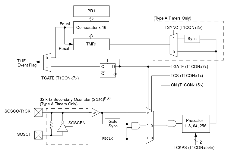
Timers of PIC microcontroller How to generate delay Circuit Diagram
The Arduino-Timer library is a community-contributed library that enables users to configure timer-based events (tasks) without the need to do register-level programming for the timer modules. It uses the built-in timer-based millis and micros functions, so it's like a wrapper layer of useful APIs on top of the built-in timer-based functions.
