Motor Driver Wiring Sketch Circuit Diagram
Motor Driver Wiring Sketch Circuit Diagram Therefore there is wide usage and request for suitable
Chase Ideas, Unlock Possibilities Zane Thatchare.
frequency counter circuit diagram Frequency Counter: Schematics and C code for a PIC frequency counter
DIY Real Time Whole House Energy Meter v12 rhomeautomation Circuit Diagram In this guide, you
Using an accelerometer for position Circuit Diagram Movement Detection. Any change in the location of
Microcontroller and circuit diagram of component Learn how to troubleshoot microcontroller interface circuits effectively by
Mosfet Switch Circuit Circuit Diagram MOSFETs exhibit high input impedance, making them versatile and adaptable
DIY Arduino GPS Tracker Project Build Your Own Location Tracking Circuit Diagram The L86 has
Pauls DIY electronics blog My New Power Supply Design Project Part 3 Circuit Diagram In
5 IoT Sensors for Every Application Circuit Diagram Our list of sensor based projects is
PDF Smart irrigation system based on IoT and machine learning Circuit Diagram AI-driven irrigation systems
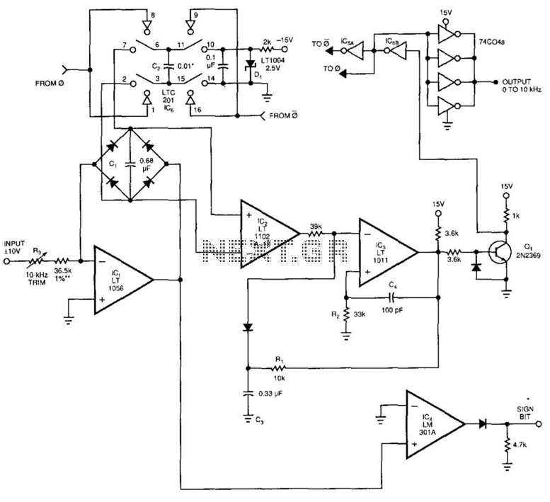
voltage to frequency circuits Converter Circuits Nextgr Circuit Diagram Here Frequency to Voltage Converter Circuit
IoT Based RFID Smart Door Lock System Using NodeMCU ESp8266 Circuit Diagram Learn how to
Bluetooth Control Home Automation copy Circuit Diagram However, what we have managed to achieve so
DIY ECG EKG Portable Heart Monitor 8 Steps with Pictures Circuit Diagram Combine a touch
Voice Controlled Home Automation Project Abstract Circuit Diagram The Voice Activated Home Automation system will
PDF Voice Controlled Wheelchair for Physically Disabled People Circuit Diagram The hardware implementation of the
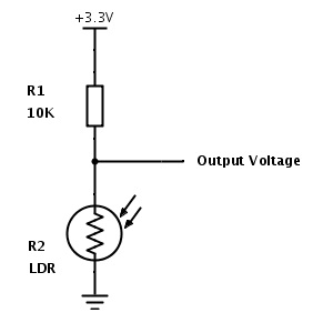
ldrexample Circuit Diagram The LDR symbol basically represents the symbol of the resistor in electronic
Transistor as a Switch Circuit Circuit Diagram It consists of an NPN transistor, a current-limiting
China Electromagnetic Relay Switch Circuit Diagram Relays are often used to control circuits through a
Schematic diagram of the voltageregulator circuit Circuit Diagram Learn about voltage regulators, their classification, design
Figure 3 from Automatic fish feeders for fish farming in aquariumsbased Circuit Diagram #fish feeder#automatic